
Hi guys, today I’m going to take you through the process of setting up your Voron 0.1 using a BTT Manta M4P and CB1 board. The Manta is a hybrid board with mounting point available for a Raspberry Pi compute module or BTTs own CB1 drop in replacement. This reduces wiring plus given the current Raspberry Pi scalping it is very cost effective too.

The Docs
The Manta boards are fairly well documented in terms of a controller board from a Chinese manufacturer. Most of these boards are normally great but the docs are incomplete, poorly translated or simply scattered all over the place. But for the Manta they were super easy to find (linked from the Aliexpress product page) and mostly complete!
In the box
The Manta comes with the following items in the box
- BTT Manta M4P and CB1 board
- JST connectors for every port on the board
- Jumpers for the motor drivers and voltage selection
- Fuses for the power inputs and bed output
- 4 x TMC2209 stepper drivers (if you ordered them)
- External WiFi antenna
- Thankyou card
- Rubber ducky!

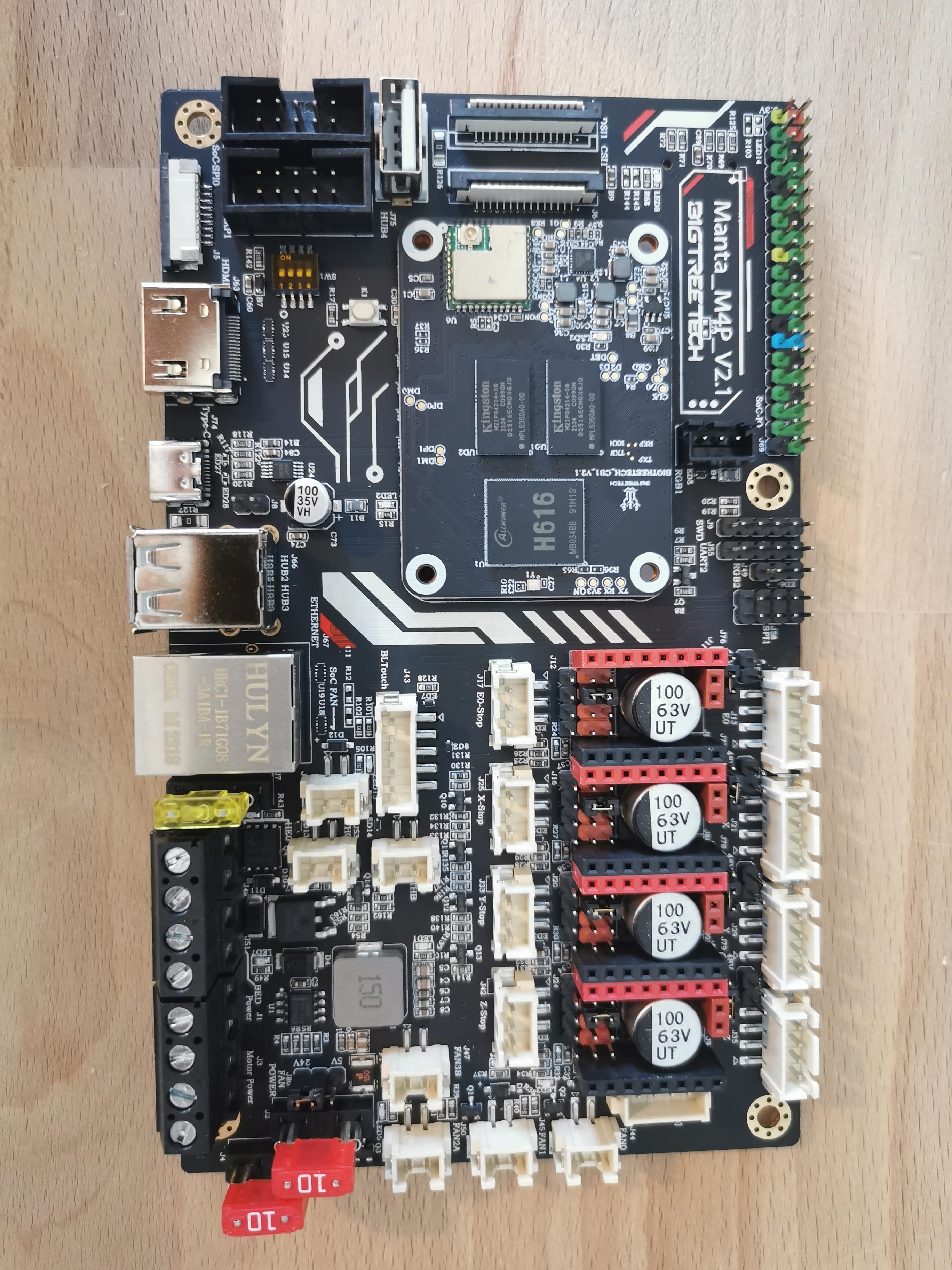
The board looks fantastic although it is larger than I would of liked for a 4 driver board. The silkscreen is two colour and someone has put the effort into some nice graphics dotted around the board. Soldering looks very neat and I can’t see any poorly installed parts. As you can see the CB1 board came pre-installed on mine.

Preparing the board
As we are going to be using TMC2209 drivers in UART mode set the jumpers as shown in the image below. My board came with them installed like this.

For this tutorial we will be using a standard 24V power supply that was originally on the Voron 0.1 so set the jumpers for the motor power supply to 24V.

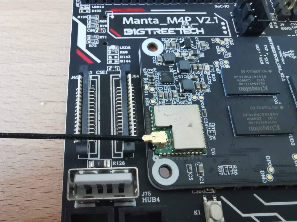
Plug the external WiFi antenna into the CB1 board.
Plug in the 3 fuses (automotive fuses) into the slots around the screw terminal block. And set the fan power to come from the 24V supply.
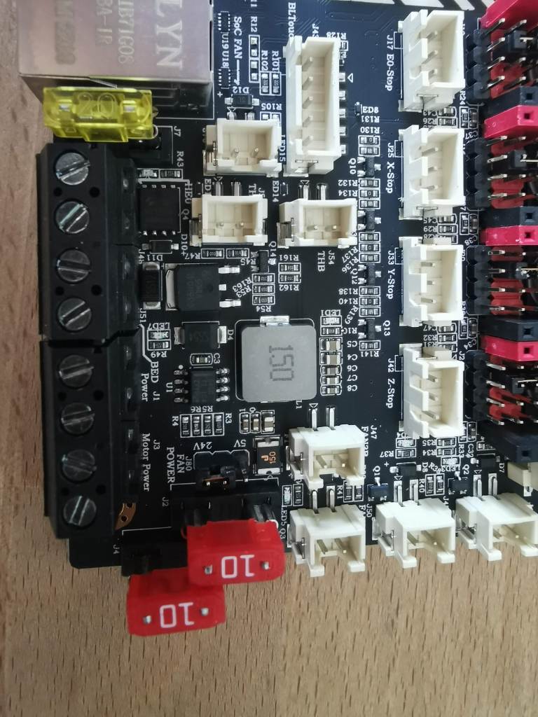
Lastly add a jumper in positioner J8 to connect the USB connector power to the boards. We will use this to provide power while we install the OS and flash the firmware before wiring the board in.

Firmware
CB1 OS + Klipper install
Use micro SD card smaller than 32Gb. Download the image from BTT github pick the latest version and download the .img.xz file.

Use raspberry imager to write the image to the SD card.

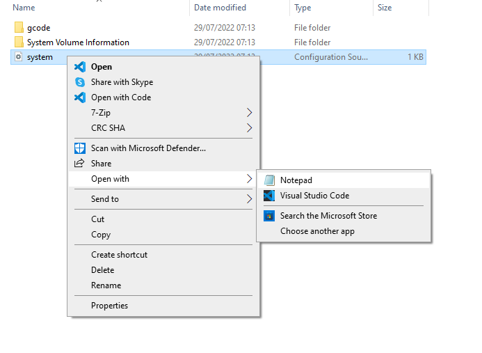
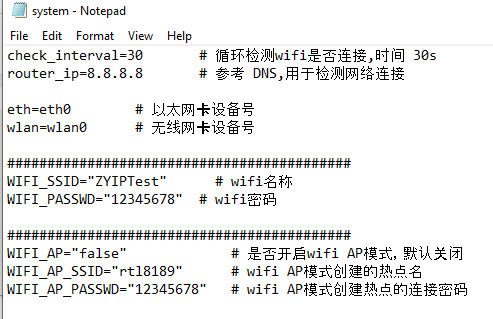
Now to configure the WiFi. The official guide says that in one of the partitions on the SD card you should be able to find the wpa_supplicant file however on my installation I didn’t get that. The video guide shows using the system configuration file and that was present so I used that. Open it in notepad.
Replace the SSID and password with that of the WiFi network you want the device to join. Save the file.
Save this file onto the SD card. It’s important to select all files as the file type and to include the .conf file ending.
Plug the SD card into the micro SD card slot. Then plug in a USB C cable to power the board. I use Advanced IP Scanner to locate devices on my network. I find you are best to do a scan before you turn the device on and then repeat it and see which one appears. They often don’t have a useful name!

For me this was 192.168.68.119. Right click on it and then choose SSH. This will open a CMD terminal. Press y to trust the SSH key for the first time.

Login with username biqu and password also biqu

We will be using KIAUH to install Klipper and the associated packages.
First off we need to make sure git is installed. Paste and run the following command. It should already be there but there is no harm in checking!
sudo apt-get install git -y
Next we want to make sure we are using the user we created earlier rather than doing everything as root. I called my user pi. Run the command below but substitute in your user in the place of pi. You should see the active user change to the one you entered.
Next install KIAUH. run these command one at a time. You should now have successfully installed KIAUH.
cd ~
git clone https://github.com/th33xitus/kiauh.git

Next launch KIAUH using the command below. You should be greeted with the menu for installing Klipper, Mainsail and Moonraker!
./kiauh/kiauh.sh
Press 1 and enter to go to the install menu. We are going to work our way through the installed in numerical order. Start with Klipper (1) then Moonraker (2) then Mainsail (3). If you are familiar with this process and know what you want you can start adding extras but otherwise you can add them later. You will likely be prompted for the sudo password during this. Enter it (note no text appears when doing so) and press enter. Installing these will take a while. Choose y for all the options as you go along. Pick the recommended python version and install only 1 instance of klipper when asked.

Once complete enter b to go back to the main menu. You should have a status that looks like this. If you do press q and exit.

Navigate to the IP address in your browser and check that you get the Mainsail dashboard appearing. You will almost certainly have a Klippy error because you haven’t defined a board yet.

Flashing the MCU firmware
SSH back into the device if you exited it (Use user ‘biqu’ and password ‘biqu’) otherwise swap to the user by doing ‘su biqu’
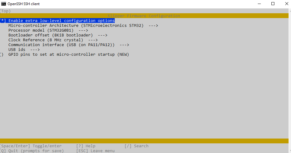
Navigate to the klipper directory and open the klipper menu.
cd ~/klipper/
make menuconfig
Change the settings to match the image below. Press q to exit and save when prompted.
Run make to compile firmware,”klipper.bin” file will be generated in
home/pi/kliiper/out folder when make is finished.
You now just need to get this file, rename it to firmware.bin and load it onto the sd card. My preferred way of doing this is to use WinSCP to copy the file to my pc and then manually move it over onto the sd card. Create a new session in WinSCP and select the SCP file protocol. Enter the IP address and user info. Leave the port as the default 22.

If successful you will get a visual display of the file system on the cb1. Go into the klipper file and the out file and copy the klipper.bin file onto your pc. From there copy it to the second sd card as you would normally.


Remove power from the Manta board and Insert SD card into the full size SD card slot. Plug the USB C cable back in to turn the board back on.
Configuring Klipper
Head over to the BTT github and copy the contents of the config file for the Voron zero.

We now need to get the board ID. Enter the command below and then copy the output and replace the one in the printer.cfg file.
ls /dev/serial/by-id/Add include mainsail.cfg to the top of the printer config file.

Uncomment the correct motor current based on the Z motor your printer has. Mine was an LDO kit.

Set sensor type for the extruder. Generic 3950 will be correct for most basic thermistors but do double check what came with your kit. Also pick the correct current based on the motor you have installed on the extruder.


Set the bed sensor type

Then click save and restart. It is time to do your wiring!
Wiring
Wiring the board is pretty straight forward. Some things to note that should help speed things up
- BTT have provided an stl for a printer mount here
- When looking from the back the right hand motor should be plugged into X
- The end stop pins need to be checked, you should wire between the signal pin and ground. Be careful as other boards use the mirrored layout and would cause a short between 5v and ground
- The board only allows all fans to be 5v or 24v. Set this to 24v and then use the 5v supply on the SPI1 connector or EXP1 connector for the supply voltage for the hotend cooling fan (the default one runs on 5v on the Voron zero!) Plug the ground end in to the control line on the fan port (FAN1)

Commission the printer
Now you should be ready to commission the printer. You want to check your motors all move in the correct directions. Try homing your printer and be ready on the emergency stop button. Watch which directions your printer goes. Use the table below to determine whether you need to switch and wires or firmware direction pins. These can be swapped by adding or removing an ! before the direction pin name under the stepper configurations.

Congratulations your printer is up and running and should be ready to do your standard printer calibration stuff! If you are unsure about this check out this reference from the Voron team

Support 3DP and ME! Help us keep producing tutorials, content and mods!
£5.00

After installing KlipperScreen (Installed!), Telegram Bot: Not installed!, Crowsnest: Incomplete! (In yellow type, no less), what should I do?
LikeLike
This is where the whole process went south for me. You say: cd ~/klipper/
make menuconfig, and hat’s supposed to get you to the place where you create the MCU edit. But it doesn’t!
LikeLike
This is also incorrect: “Run make to compile firmware,”klipper.bin” file will be generated in
home/pi/klipper/out folder when make is finished.” What one should do is Q / quit, which automatically SAVES the klipper.bin file. Then you have to get it, rename it, and put it INTO MAINSAIL (at least that’s what I know from Rolohaun).
LikeLike
It’s not incorrect you need to run the make command for it to generate the bin file.
That said you are correct it sort of assumes a few steps such as exiting the config menu and saving when doing so
LikeLike
What does this mean? “If successful you will get a visual display of the file system on the Gemini.” What is “on the Gemnini?”
LikeLike
This is a good point that is a typo/ommission in removing it!
LikeLike
You wrote: “Remove power from the Manta board and Insert SD card into the full size SD card slot. Plug the USB C cable back in to turn the board back on.” What about the micro SD card that’s still in it’s carrier? Should I have removed that after I pulled the power off the board? Should I remove it now? Or should I leave it in there (because the Hurakan needs that card to do it’s thing?)?
LikeLike
Leave it there 🙂
LikeLike
This is what really messed me up! You wrote: “We now need to get the board ID. Enter the command below and then copy the output and replace the one in the printer.cfg file.”
Enter the command WHERE? (I recognized the command and knew that it is used in PUTTY’S Command Line Editor, but that’s because I’ve seen this process before in Rolohaun’s series of videos on putting Klipper on the RPI / Raspberry Pi.)
Still, I think the lack of explanation at this point in your webpage will make people CRAZY!
LikeLike
Erm apologies maybe I am assuming too great an understanding of my readers.
But you are correct using it in the open putty ssh terminal session is correct.
LikeLike
You wrote: “ls /dev/serial/by-id/.” But I think you forgot that you’re IN KIAUH, which is a MENU-BASED program. Instead of typing that code at the “Perform action:” prompt, you need to enter 5, ENTER. The MCU ID will appear about the box called “Advanced Menu”
LikeLike
This is true, but that feature wasn’t always there. I’ve always used the command line option
LikeLike
Thank you for getting back to me on all of my snarky comments. Putting firmware that I have to make on control boards for 3D printers is my least favorite job in the whole wide world. Right now I’m trying to figure out why my 7” monitor isn’t working on my BIQU Hurakan. It worked with version 2.2.1 three months ago, perfectly! Then the printer fried itself to death because of a floating ground on the FG post of the PSU.
LikeLike